Written by: Rob Zulian
 Additional Information: Russell Ziegler
 Additional Information:
Marcus, aka Boxrodz Additional Information:
Marcus, aka BoxrodzIf you have ever driven a
73-87 GM truck at night you know one thing, the stock lighting leaves
something to be desired. Dull, dim yellow light just doesn’t cut it in
today’s world with the latest advancements in lighting. Halogen bulbs that
were the best you could get 10 or 20 years ago, but they cannot match the
latest stuff coming out of Detroit on the newer cars and trucks. To improve
your trucks lighting, options include upgrading to Silverstar sealed beams,
or the latest trend would be replacing the sealed beams with an H4
conversion bulb. Both of the options will increase the light output, but
not as much as possible due to the limits in the stock GM headlight
wiring.
The stock headlight circuit
is very inefficient for delivering voltage to the headlights. Power flows
from the battery, through the firewall junction block, to the headlight
switch, then to the hi/lo switch and then back out to the lights. Add up
the total resistance of this circuit and you end up with less than the
available system voltage. In my case on my 75 Blazer, the available voltage
at the lights was over 1 volt less than the available system voltage
measured at the alternator. This is why most lights on these trucks are
dim, add any corrosion or other wiring issues and yours could be less.
Think about this. Assuming that 12.6 volts where you
receive 100% of your light output, look at this quick comparison chart
showing light output percentage as compared to the voltage the lights are
receiving:
12.6 V = 100%
11.5 V = 75%
10.3 V = 50%
8.7 V = 25%
According to the chart, you’d only be getting approx 50% of your possible
light output at 10.3 Volts!
To correct this problem and
provide more voltage to the headlamps, a simple change can be made to the
wiring. By adding relays to the system you can use the stock lighting
circuits (hi/lo) to remotely turn on relays that are connected to direct
battery power for the simplest circuit possible. And, by using
a larger wire gauge (14 AWG or greater) than that which
is used in the stock wiring (18 AWG/16 AWG), the voltage loss at the
headlamps may be further reduced. Follow along and I’ll show
you how I did this on my ’75 K5 Blazer.
LMC Truck now sells a
kit to do this, but when I wanted to upgrade mine it was not out yet.
Keep in mind that my setup
is for a ’75 model year and should work for all ’73 to ’80 single headlamp
setups. It will work for single headlamp setups from ’81 and up also, but I
have not verified the wiring colors on these trucks. Dual
headlamp (4 total) operate similar to the single headlamp setup with 2 lamps
lighting up under the low beam mode while all 4 lamps
lighting up under the high beam mode.
Items you will need:
2 30 amp relays
2 30 amp inline fuse assemblies
2 rolls of 14 GA wire (2 different colors)
1 package of shrink tubing (for 14 GA wire)
1 package of female spade connectors (I got the weather proof kind with heat
shrinkable ends) get at least enough for 4 connections at each relay!
1 package of ground eyelets
Tools you will need:
Wire cutters/strippers
Soldering iron and solder
Heat gun or lighter for shrink tubing/spade connectors
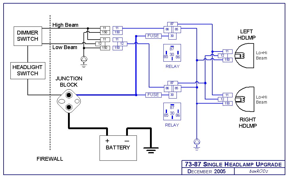
Single
Headlight Schematic (click image for larger view)
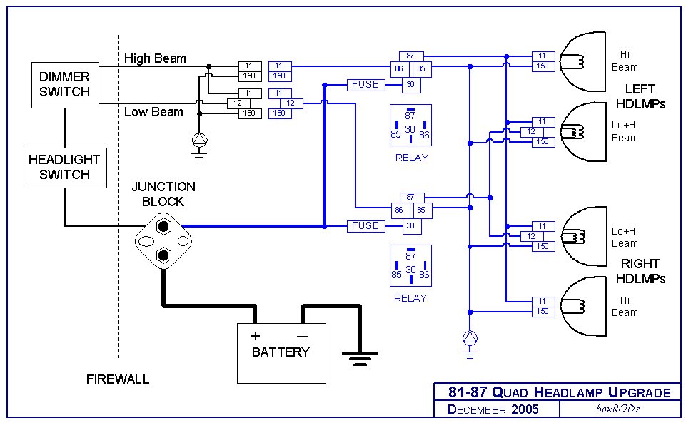
Dual Headlight Schematic (click image
for larger view)
Here's what I did. I
planned on putting the relays directly above and behind the d/s headlamp on
the backside of the radiator support. I did this for two reasons, ease of
access (not hidden by the battery) and it’s close to where the headlight
wiring comes from the fender/cab. Knowing where I wanted to put the relays,
I could set the length of wire I needed to power up each relay as well as
the ground wires for the relays. I decided to pull the power from the
junction block on the firewall (just above and to the left of the brake
booster), as I hate having a billion wires tapped off of the battery. I
routed the wires in the same split loom that the stock headlight wiring ran
in on the inside of the d/s fender. This way it's all hidden except where I
put the inline fuses nearest the junction block. To add the inline fuse
holder to the circuit I spliced the wires, soldered the connection and
covered the connection with the shrink tubing. I could then hook up the
power wires to the 30 terminal on the relays (keep the fuses out so you
don't have a hot circuit to play with). I then hooked up the ground wires I
made up with the female spade on one end and the ring terminal on the other
to the relays and ground on the radiator support.
Now we need to get the switched on signal to the relays and output to the
lights. I cut the brown and green wires that led to the d/s headlamp (don't
make the cut in the wires to the p/s bulb, see the important note below).
Each wire is still used; just the relays will be in between the where the
circuit was cut.
****VERY IMPORTANT: The stock headlight wiring is set up in a parallel
circuit. If you notice at the d/s headlamp the lamp connector will have two
of each wire (brown and green) going to it. If you peel back the conduit
you will see that one set of the brown and green wires actually goes to the
p/s headlamp. This is a clever little wiring trick the GM engineers did to
eliminate having 4 wires from the dimmer switch to the lights. Still before
and after this mod, if the d/s headlamp bulb fails the p/s light will stay
lit. (Not like a cheap set of Christmas tree lights!)
With the brown and green wires cut, add the female spade connecters on both
sides of the cut, on the switch side and the side going to the d/s light.
Depending on where you made the cut, you might have to add a few inches to
each side of the brown and green wires to allow enough slack in the wires
for easy connection to the relays (try and use the same colors if you can to
limit confusion later!). Following the schematic, you then hook up the
brown wire from the switch side to terminal 86 on one relay and then the
other brown wire to 87 terminal of the same relay. Do the same for the
green wires to the same terminals on the other relay and you are done with
the wiring. Secure the relays to the radiator support, making sure you got
all connections tight and recheck your connections to the relays. You
should have both brown wires to one and green to the other. If you have a
brown and a green wire to each relay, your dimmer will work backwards.
Stuff the wires back into conduit/split loom, put the fuses back in the
inline holders and hit the switch. LET THERE BE LIGHT!
One thing I would like to change on mine after seeing the LMC harness is the
connections to the relays. Having 1 connector with 4 terminals to the relay
would look a lot cleaner than 4 individual spade terminals. Plus you would
be less likely to reconnect it wrong if you ever had to replace a burnt out
relay.
You can see the one major difference in my setup to the LMC kit is that you
cut the wires to the d/s headlamp and use the existing headlamp
wiring/sockets whereas the LMC kit does not have any cutting and supplies
new wiring/sockets for the headlamps. This is your call if you want to cut
your stock harness. The LMC kit is quickly reversible, take the stock
headlamp socket from the LMC kit and plug it back to your headlamp to go
back to stock. This is a bonus if you are out in the boonies and a relay
quits. My setup can be changed back to stock, but you have to splice the
two wires back together. I'll carry an extra relay with me if one was to
fail.
One other thing, since my setup uses the stock wiring at the bulbs, you
might be inclined to ask why with the smaller stock wiring? I used mine,
because the stock wiring was free of any corrosion (benefits of Colorado not
using salt in the winter) and the resistance was just as low as the same
length of 14 gauge wires. That and the fact that the wiring for the p/s
lamp was tucked well under the top of the radiator support and I was too
lazy to fish it out. Basically, this is a judgment call for you to make.
If your stock wiring is thrashed and corroded, rewire the lights with fresh
wire and new connectors. Rewire it just like it was factory so you don't
have two wires crammed into one terminal at the relay.
Overall, the modification
is fairly simple to do and is inexpensive as well. You will be amazed at
the increase in light output…even if you don’t upgrade to H4 bulbs. If you
do plan on adding H4 conversion bulbs it is a worthwhile upgrade to get all
the output possible from your new bulbs.
DISCLAIMER:
USE THIS AS A GUIDE. Your wiring colors may vary by year of truck. Use
the GM service manuals for the stock schematics on the later trucks
(Chilton’s or Haynes are not perfect in this area). If you don't have access
to a GM manual, break out the test light and verify the color/purpose of
each wire yourself.
Home
|